Description of circuit addition for electric car charging.
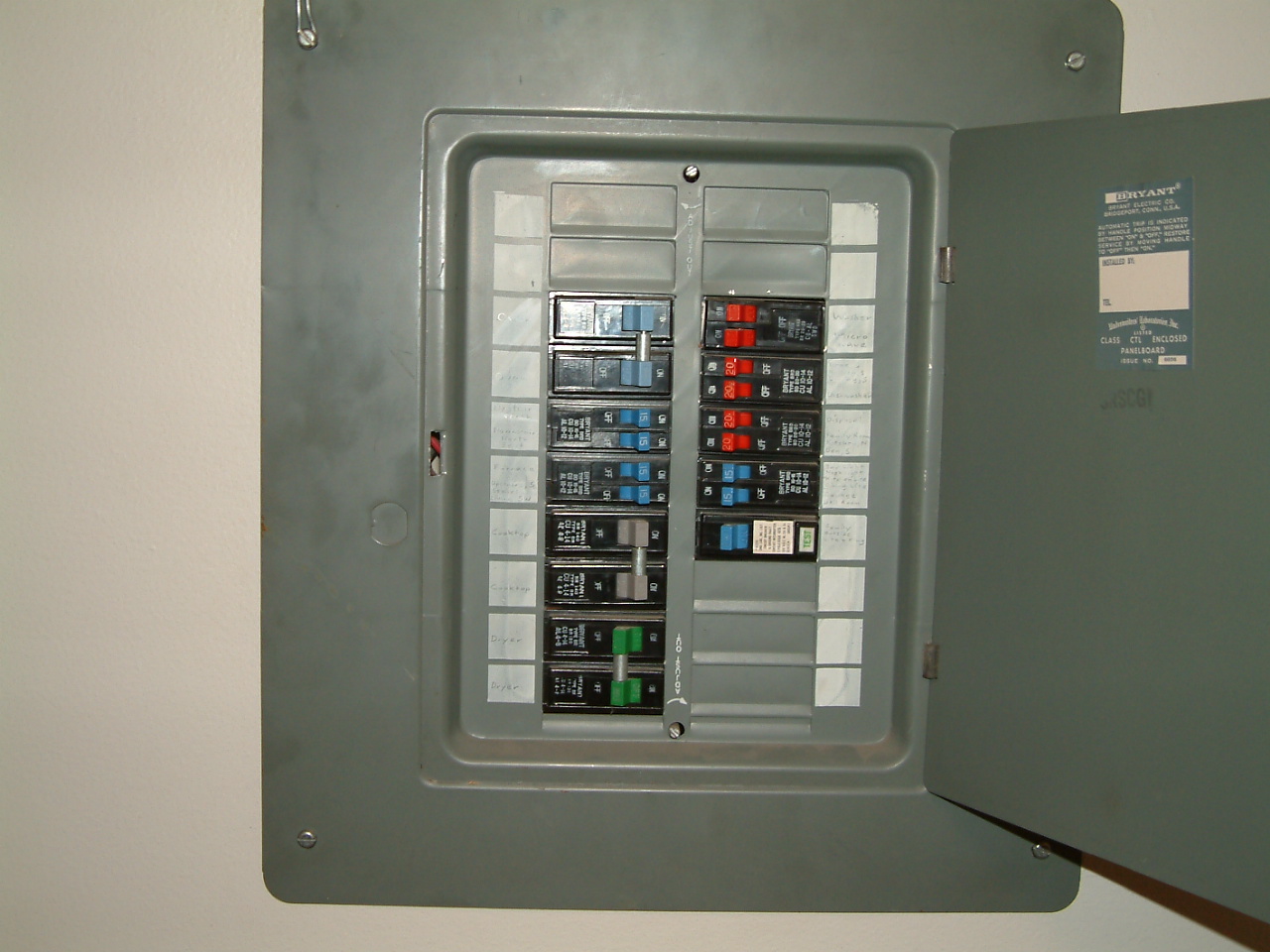
Above is the subpanel that is in the utility room. It is roughly 25 feet
from the main electrical panel, which is in the garage.

The 110 volt circuits in the subpanel are
  Left column
    15 A - Upstairs North
    15 A - Downstairs North & East
    15 A - Furnace Fan (gas furnace)
    15 A - Upstairs South, stair well
  Right Column
    20 A - Washer (and gas dryer)
    20 A - Refrigerator
    20 A - Nook S, Kitchen S
    20 A - Dishwasher
    20 A - Disposal
    20 A - Family room N, Kitchen N, Den S
    15 A - Bar light, Nook light, Kitchen light, Dining room light
    15 A - Garage, utility room light
    15 A - Ground fault breaker, single outlet in back of house
Most of the lights in the house now have LED bulbs, which draw about 15%
of the electricity that was once drawn by incandescent bulbs.

The 220 volt circuits in the subpanel are
    50 A - Oven. This was a double oven, but is replaced with a single
           oven+microwave that only calls for a 30 amp circuit.
    40 A - Cooktop
    30 A - Dryer. Circuit is not used (we have a gas dryer)
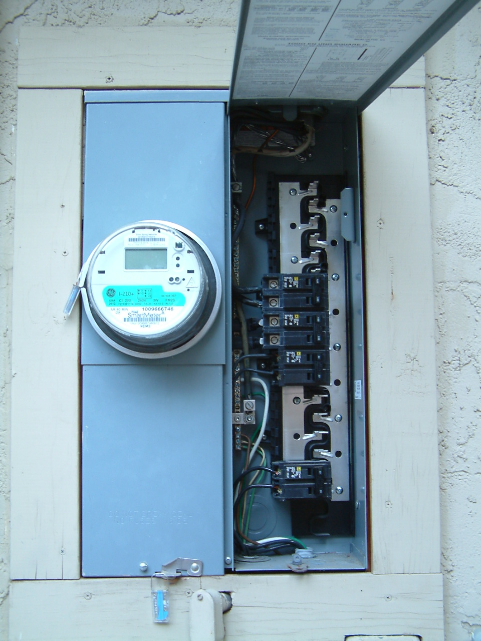
Above is the main panel. If one faces the garage door from the outside,
this is just around the corner on the right. Only four of the available
nine circuit breaker "slots" are in use. On the inside of the cover
plate, it says "Mains 125A max."

The circuit breakers on the right are, from the top:

1. 100 amps. Feeds the subpanel in the utility room. This circuit's
   cable goes out though the top of the box. There is no other knockout
   on the top of the box, but there are three free knockouts on the
   bottom of the box.

2. 100 amps. From the meter on the left, feeds the bus bar. So this is
   the master breaker, not a branch circuit.

3. 30 amps. Goes to pool equipment. These wires exit the box at the
   bottom, and you can then see the associated conduit come out through
   the wood framing, slightly left of center, at which point the conduit
   goes straight down into the cement walkway below the meter, and off
   to the pool equipment. Although the circuit can in theory deliver 30
   amps times 240 volts, or 7200 watts, the pool now has a high
   efficiency variable speed pump that normally draws less than 500
   watts except when the pool solar is active, in which case it draws
   around 1100 watts (about 5 amps @ 240 volts).

4. 30 amps. This breaker is below two empty positions on the bus bar.
   This circuit ultimately goes to 22 panels of photovoltaic roof solar,
   so it is a source of electricity, not a sink. The associated wires go
   out the bottom of the box, which puts them inside the garage. The
   garage is NOT "finished off" with wallboard, which, of course, makes
   the wiring much more accessible. As the picture below (of the back of
   the main box, in the garage) shows, this circuit's wires travel out
   the bottom of the box, through 3 holes drilled through 3 2x4's, and
   into the bottom of a "solar" subpanel box on the left in the picture
   below. The solar box has a four 120 volt 15 amp breakers, coupled in
   pairs as two 240 volt breakers. From this box, the wires go up to the
   array of 22 photovoltaic solar panels on the roof. The solar
   installation is based on Enphase M215 micro inverters, with an
   inverter for each solar panel mounted under the panel, such that each
   panel offers an 120V AC output that can be connected in parallel with
   others, and can be directly connected to the power grid, after two
   120 volt circuits (of 5 or 6 panels each) have been joined via a
   shared "common" so as to form a 240 volt circuit. The micro inverters
   are such that they make an "under performing" (e.g., currently in the
   shade due to a tree, for example) panel still produce a full 120
   volts, but with less current, with the effect that an under
   performing  panel "contributes what it can," but does not drag down
   the efficiency of, or have any other effect on, the other panels in
   the system. (Configurations not using micro inverters typically have
   a problem that one panel not performing well -- wired in series with
   others -- can reduce the effective output of other panels that are
   wired in series with the poorly performing panel.)
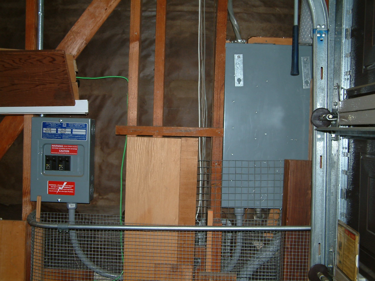
Above is the backside of the main panel, the front of which is displayed
in the previous picture, as seen from inside the garage. I've built a
structure to hold spare wood in the same corner of the garage as the
main panel, and that structure blocks out some of the view of the bottom
of the main box in the above picture. I will take this structure down
temporarily to allow work on the wiring, but had not done so before
taking this picture. The bottom of the main box is accessible from
inside the garage when the spare wood containing structure has been
taken down.
The smaller circuit box to the left is associated with a rooftop solar
installation, which I noted earlier.
The intent is to add one new 50 Amp 240 volt circuit, via a breaker in
the main box, for the purpose of charging an electric car. The circuit
will terminates in a NEMA 14-50 connector. The circuit will be installed
with number 6 wire, since it has a 50 amp plug, but (a) the current draw
will occur between 11 PM and 6 AM -- a time interval when electricity is
cheapest and virtually nothing else in the house is drawing any current,
(b) be limited to 24 amps by the charger, and (c) will usually be lower
than that. Ultimately, electric cars, like regular cars, DO use a lot of
energy over time, so the number 6 wire, while oversized for a 24 amp
job, will be helpful in terms of minimizing (I**2)*R ("I squared R")
energy loss in the wiring.
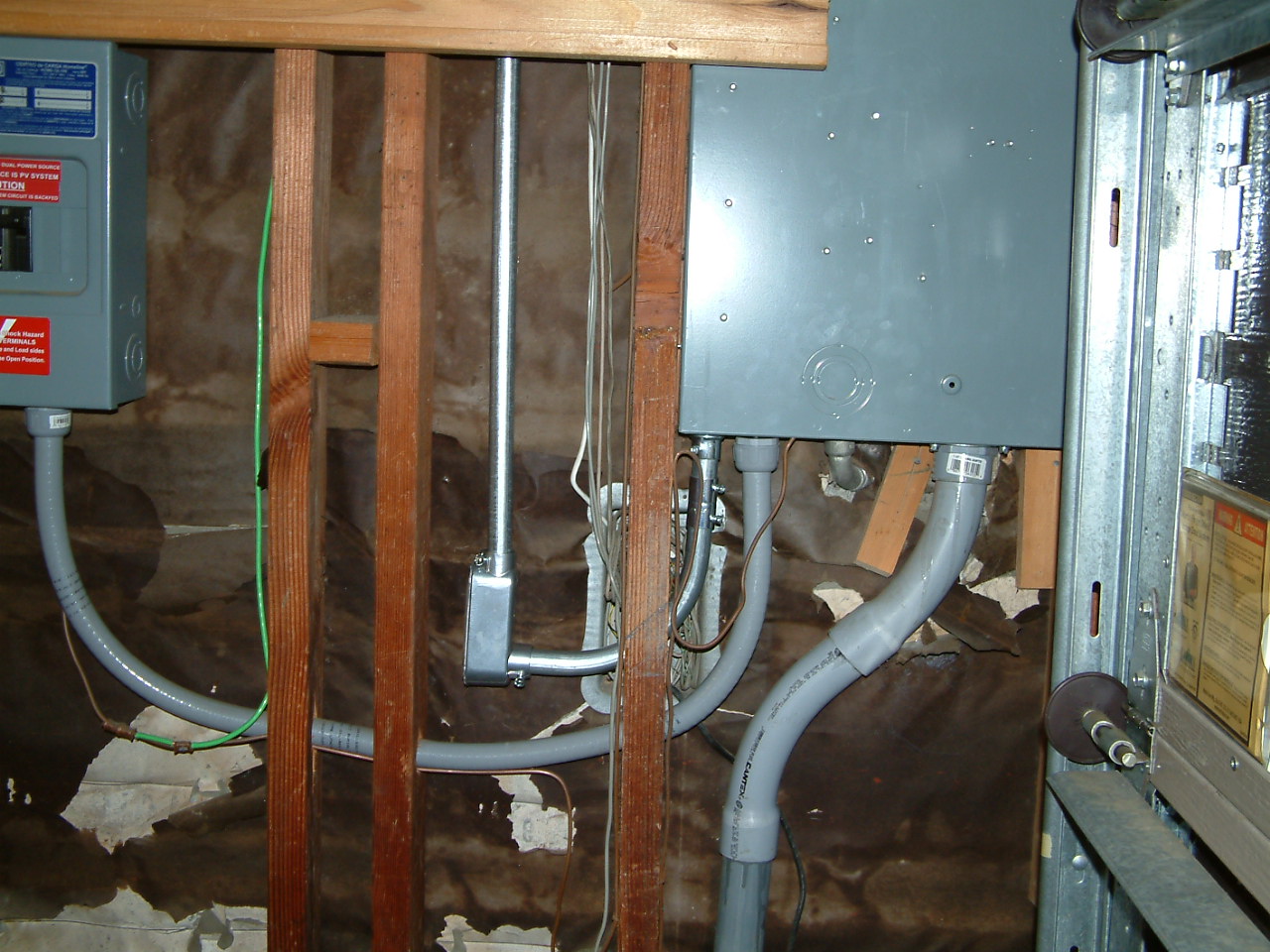
The wires from the new breaker must come out of the bottom of the main
box, which is accessible in the garage when my spare wood containing
structure has been taken down. There are no free knockouts in the top of
the main box. There are 3 free knockouts in the bottom of the main box.
Two of them are smaller, towards the front of the box, and access to
them is partially blocked by stucco, which would have to be removed
before those knockouts could be used. The third knockout is directly to
the left (in the picture) of the solar circuit's flexible conduit that
leaves the bottom of the box and heads over to the solar panel.
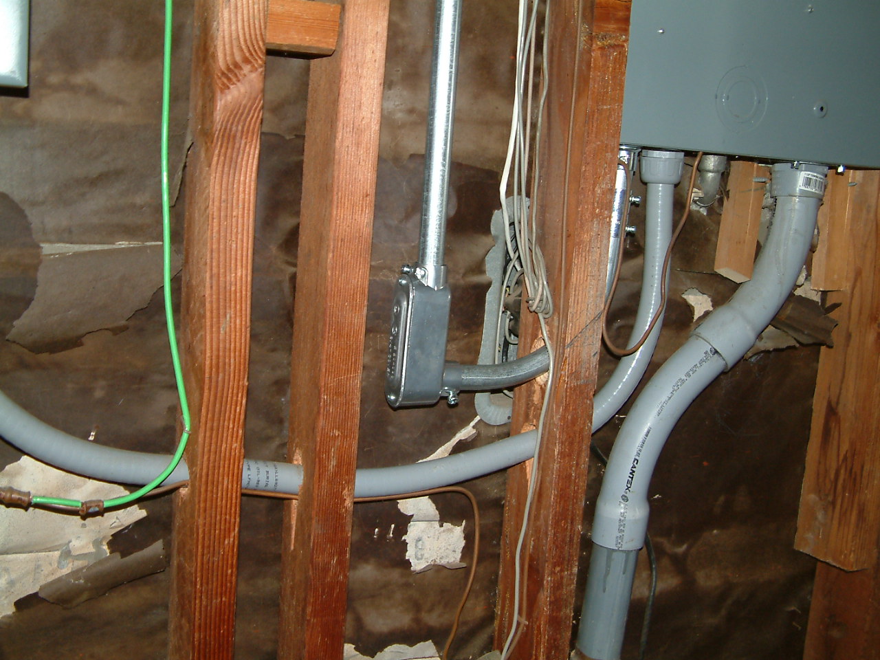
After leaving the bottom of the main box, the new circuit will head
towards the solar box, much like the solar wiring does, but will need to
go through only one 2x4, rather than 3 2x4's, as the solar circuit does.
But it is very crowded in the area where the new circuit must come
through. The solar circuit "flexible conduit" adds to the crowding, and
telephone circuit wiring has been placed in the same area, adding to the
crowding. This makes drilling the required hole in the 2x4 is the most
difficult part of this project, because space is so tight.
To deal with this, I purchased a "right angle" electric drill adapter
(from Harbor Freight Tools -- at a cost of only $20) and a very short
drill bit, for drilling the required hole.

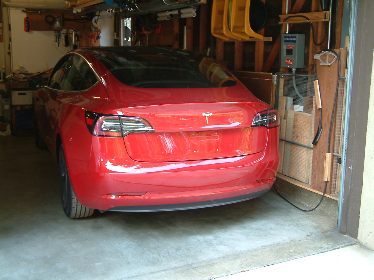
The above picture shows the completed project, with everything put back
together, including my structure for holding spare wood remnants. There
are more pictures below showing details of the routing of the new
circuit, but this picture shows our ultimate objective, and how it
worked out.

In this picture, you can see some of the new EMT conduit, leading up to
a new NEMA 14-50 plug. Plugged into that plug is the standard Tesla
charging cable ("2nd generation") that comes with a Tesla. I have routed
this cable to the left of my wood storage structure, where it then comes
down to the ground, heads a ways to the right, and, in this picture,
hangs on a board which I have put in place specifically to provide a
place to hang the charging cable when not in use. The board has two
attach pieces of wood which "channel" the cord -- the first to insure
that the cord does not interfere with the "electric eye" obstruction
detector associated with the garage door opener, and the second of which
leaves the charge cable connector hanging against the wood board, rather
than against the scratchier wire screening used in my wood storage
structure. The cord hangs over a plastic garden hose "hanger," which has
been trimmed in width.
In the above picture, and the two pictures below, you can see the detail
of the EMT conduit routing for the new circuit. The curved piece which
actually goes through the 2x4 is a "stock" 90 degree turn piece, so it
did not require any bending to be done by me.

Barely visible in the above picture, but more clearly visible in the two
pictures below, is a pencil line on the 2x4 which shows the upward angle
of the hole (if drilled from the left) though the 2x4. If you project
that line, it is clear that the flexible conduit -- put in place during
the solar installation -- prevents one from getting a drill in there ---
and does so even more than the limited spacing between the 2x4's.
Drilling the hole would have been impossible without the "right angle"
drill adapter from Harbor Freight. On top of that, this particular 2x4
was very old, dry, dense, and nearly "hard as cement." So just drilling
the hole was quite an effort.
Above is more detail of the conduit going through the newly drilled 2x4
hole, showing that it is just below an existing "lump" of telephone
cable wiring.
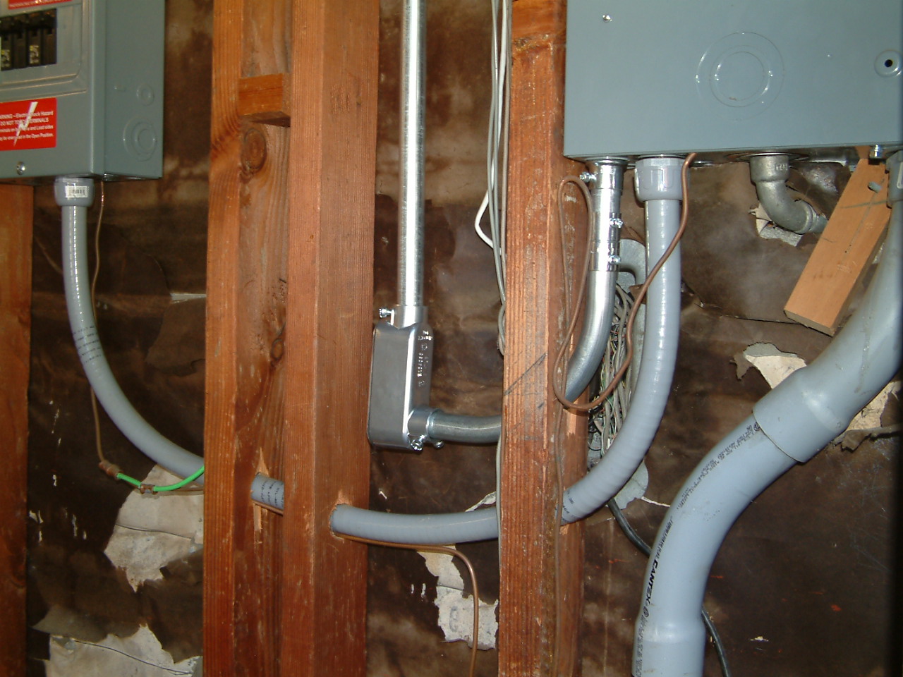
Above is more detail of the conduit going through the newly drilled 2x4
hole, showing the crowded quarters.

The above picture shows the Tesla Model 3 in the garage, being charged.
Noteworthy (perhaps) in this picture, is that the Tesla driver's door is
FULLY opened, and still clears the Prius V also parked in the garage. As
the cars are parked in the above picture, the Prius doors can also be
FULLY opened (on the drivers side), while clearing the Tesla. As parked,
the Prius doors on the passenger side clear the cabinets on that side by
a bit more than 23.5 inches, so one can get in on that side, but one
can't open the doors fully.

If you look on the far wall in this picture, roughly midway between the
two cars, there is an unpainted wooden board about 16 inches wide and 36
inches high, which is mounted on the wall, and which contains two 9
circuit controllers which control watering lines on the property (the
controllers are black, but with a silver colored section in the middle).
In the lower left corner of that board, you can see a red light, which
was lit up when I took the picture. This red light is controlled by the
garage door's "electric eye," which senses things in the entry area to
the garage, so as to prevent the garage door from being closed on
objects that are in the door's closure path. I use this light when
parking the Tesla to insure that the Tesla is far enough into the garage
so that the garage door will not close on it. The light is also used
when parking the Prius in the garage.
The above picture shows the Tesla in the garage, but with the charging
cord hung up on the board provided for that purpose.
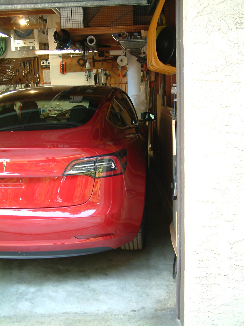
The above picture shows clearance on the right side of the Tesla. As one
drives into the garage, one must be sure that the Tesla's right mirror
clears the garage door frame, and clears at one other point, which then
leaves plenty of clearance for the rest of the Tesla. But the Tesla has
various proximity detectors which "get upset" as the car is being
parked, and the car does "scream" (about possible impending impact) big
time, as one puts it in the garage with, say, only an inch or so
clearance for the right hand mirror. That makes it a bit unnerving just
to put the car in the garage as indicated in the picture, but I'm sure I
will get used to it.

The above shows the Tesla outside of the garage being charged. Not shown
is a blocking "slider" that I have installed for the garage door
"electric eye," which blocks the "electric eye"'s light path, to
insure that the garage door stays open when doing things like this.

In routing the Tesla cord from the NEMA 14-50 outlet down to the floor,
the cord can easily be "pulled off" of the various "elements" that route
the cord's path down to the floor. This gives the cord about another 10
feet in "reach" than is the case for what is shown in the picture, for
charging cars that are not in the garage.

(I am enjoying my Tesla, big time. It is a delightful car to drive. Very
reminiscent of our old (and also red) Honda CRX HF, where one sat very
low to the ground. The Tesla handles similarly, but, of course, the
Tesla has much more power. And it is a four door sedan, rather than a 2
seater like the CRX. The Tesla is the two wheel drive (rear wheel drive)
model with a "long range" battery, which gives it about a 310 mile range
on a single charge.)